|
查看:
1178
|
回复:
1
|
TI M0开发板测评报告 简单点个灯
|


劉啟迪QidiLiu
1
主题
4
回复 |
1#
电梯直达

整体使用评价
抽到的是MSPM0L1306,第一次用德州仪器的单片机,还可以。
开发项目流程
0. 环境配置
根据官方教程:Quickly get started with MSPM0 MCUs。先下载并安装了MSPM0-SDK — MSPM0 Software Development Kit (SDK) 和 CCSTUDIO,详见MSPM0L1306官网资料
以及参考这个MSPM0 设计流程指南,发现支持用XDS110和J-Link烧录,现买了个J-Link
1. 编程、编译与上传
1-0. 编程
作为入门项目,先在CCSTUDIO中找到驱动LED灯的GPIO案例
1-1. 编译与上传
直接上传发现出错,因为默认使用XDS110,而我用的是J-Link
根据Using Segger programmers with MSPM0,安装了J-Link驱动,并在CCS中设置好。
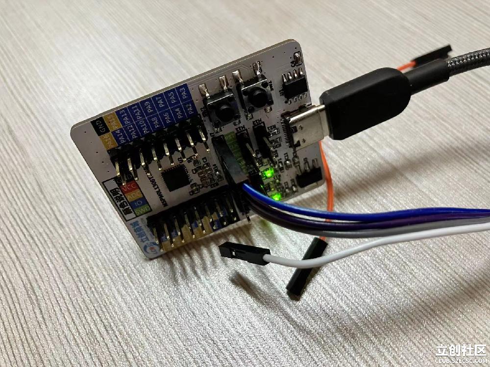
成果展示
示例代码的main()部分:
#include "ti_msp_dl_config.h"

/* This results in approximately 0.5s of delay assuming 32MHz CPU_CLK */
#define DELAY (16000000)

int main(void)
{
    /* Power on GPIO, initialize pins as digital outputs */
    SYSCFG_DL_init();

    /* Default: LED1 and LED3 ON, LED2 OFF */
    DL_GPIO_clearPins(GPIO_LEDS_PORT, GPIO_LEDS_USER_LED_2_PIN);
    DL_GPIO_setPins(GPIO_LEDS_PORT, GPIO_LEDS_USER_LED_1_PIN |
                                        GPIO_LEDS_USER_LED_3_PIN |
                                        GPIO_LEDS_USER_TEST_PIN);

    while (1) {
        /*
         * Call togglePins API to flip the current value of LEDs 1-3. This
         * API causes the corresponding HW bits to be flipped by the GPIO HW
         * without need for additional R-M-W cycles by the processor.
         */
        delay_cycles(DELAY);
        DL_GPIO_togglePins(GPIO_LEDS_PORT,
            GPIO_LEDS_USER_LED_1_PIN | GPIO_LEDS_USER_LED_2_PIN |
                GPIO_LEDS_USER_LED_3_PIN | GPIO_LEDS_USER_TEST_PIN);
    }
}
|
|


 发表于2024-01-22 18:33:34


 收藏
收藏
